As you learn more about building design, you’ll likely encounter seismic (or earthquake) loading and wonder how they factor into it.
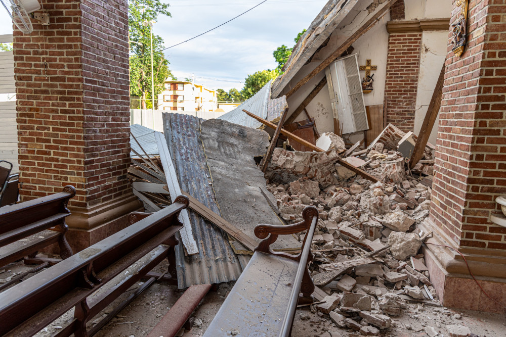
In essence, seismic loading is the load imposed on a building when the earth shakes during an earthquake. For design purposes, we consider it as a lateral load since it tries to move the building sidewise. In our design practice, we design structural elements to resist this load.
Seismic loading at its core is affected by three factors: the weight of the building, the movement of the earth, and how the building responds to the movement. Multiple methods are used to calculate the seismic load on a building. The most common method is the Equivalent Lateral Force (ELF) procedure, which is discussed here. For more complex structures, dynamic analysis methods are used.
The weight of the building is straightforward, including:
- Dead load – Weight of all the materials in the building, the structure, the finishes, heavy mechanical loads etc.
- Live Load – Weight of all occupants and any movable/changeable objects in the building. Live load is not always 100% included and is dictated by the building code.
- Snow Load – Weight of the snow on the building, where applicable. Again, only a portion of the weight is included as dictated by building codes.
Calculating the effect of the earth’s movement and building response is trickier and the main focus of seismic load calculations. Multiple factors condense down into what is known as the seismic response coefficient.
Seismic Response Coefficient (Cs)
The seismic response coefficient is based on:
- How the ground moves:
- Design Response Spectrum
- Seismic Design Category (SDC)
- How the building responds to the movement
- Fundamental Period of the building
- Seismic Force Resisting System (SFRS)
Ground Motion Factors
These are the factors that are used to determine how the ground moves during a seismic event. They are a combination of information from past earthquakes and the behavior of the soil under the building.
Design Response Spectrum
The design response spectrum is based on the following factors:
- Site Classification – the spectrum of soil types possible under a structure. Hard bedrock is classified as type A meanwhile type F is a particularly soft soil requiring site-specific analysis. The stiffer the ground, the less it shakes the building and thus the lower the seismic load.
- Risk-Targeted Maximum Considered Earthquake (MCER) – the two factors from this are:
- Ss – Mapped Spectral Response acceleration for a short (0.2sec) period
- S1 – Mapped Spectral Response acceleration for a 1-sec period
- Site Coefficients – Fa and Fv. These are used in tandem with the site classification, Ss, and S1 to get the following factors:
- Modified Spectral Response Accelerations (SMs and SM1)
- Design Spectral Response Accelerations (SDs and SD1)
Seismic Design Category
The seismic design category (SDC) ranges from A, very low seismic risk, to F, high seismic risk. It is based on the following factors: building risk category (I, II, III, or IV), S1, SDs and SD1.
SDC is used to determine the following:
- Permitted Seismic Force Resisting System (SFRS)
- Building height limits
- Permitted lateral analysis procedure. Building in higher categories cannot always use the ELF procedure.
- Restrictions on geometrical irregularities in the building.
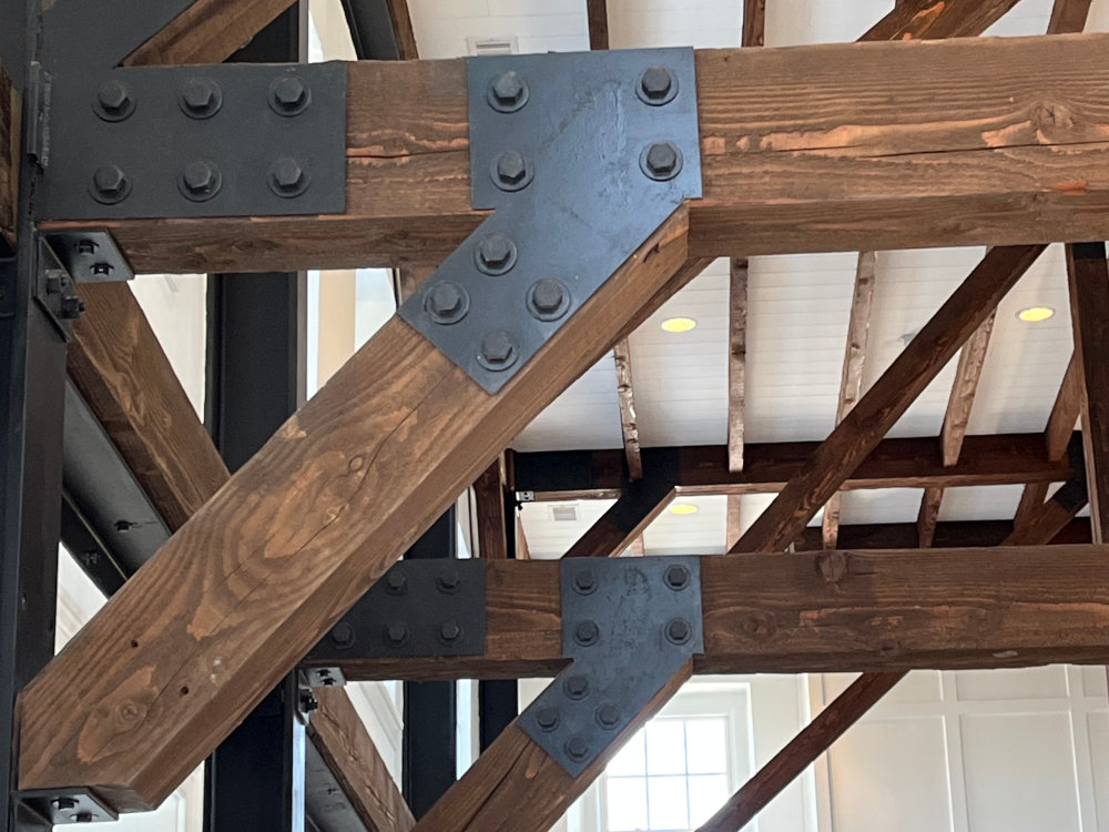
- Requirements for seismic detailing. Sometimes additional care must be taken with connection design and detailing to allow for more ductile behavior.
- Requirements for non-structural components.
Building Response Factors
These are the factors used to determine how a building will respond to the movement of the earth. Most of them are empirical factors determined by extensive testing.
The Fundamental Period
This is how the building vibrates when the ground moves and is based on the height and stiffness of the building. There are 3 ways to calculate it:
- General Approximate Method
- Approximate Method for Masonry or Concrete Shear Walls
- Rational Analysis method
The general approximate method is the most commonly used. It is an empirical equation given in the building code. It is based on the height of the building and the SFRS used.
Seismic Force Resisting System (SFRS)
This is the structural system used to resist lateral loading. Six major categories exist with subclasses based on the material used and the design needed for requisite building ductility. These categories are:
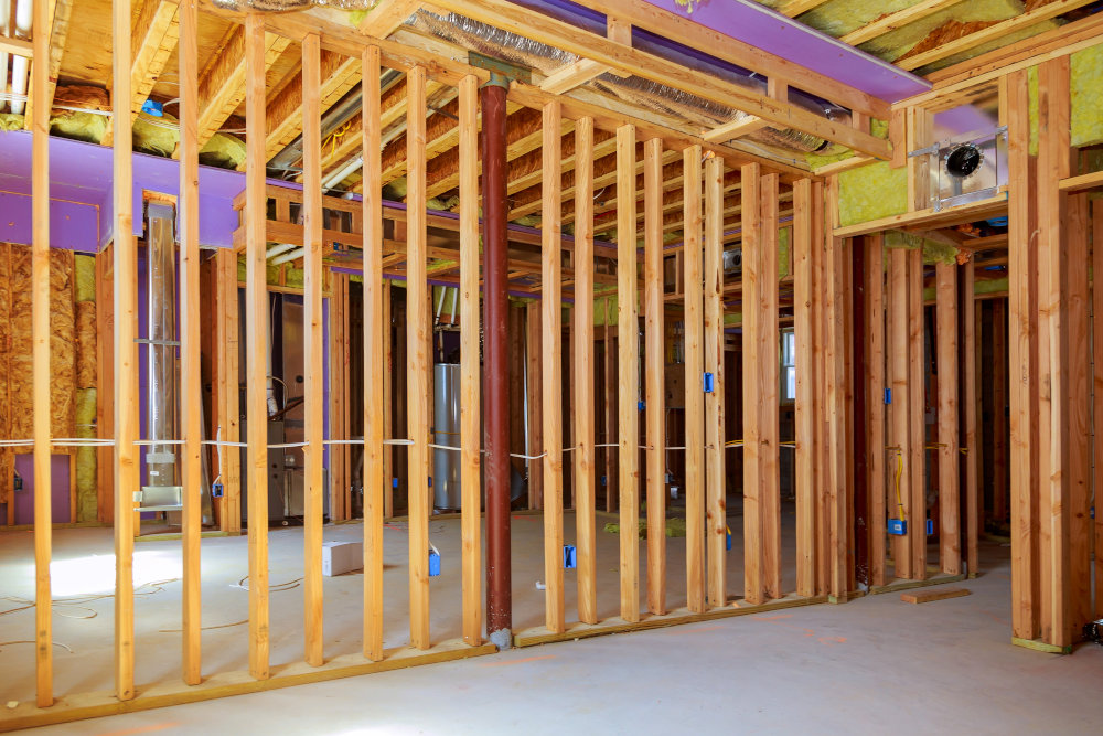
- Bearing Wall System – A system where the walls support lateral and gravity loading. Most commonly used in residential design.
- Building Frame System – A system where gravity loads are supported separately from the lateral loads. Typically, gravity is supported by an infilled frame meanwhile lateral loading is supported by shear walls or the aforementioned infilled frames.
- Moment-Resisting Frames – A complete space frame with rigid moment connections used to support gravity and lateral loads.Dual System – Special Moment Resisting Frame with Building Frame System – A dual system where a moment frame supports the vertical loads and shear walls or braced frames resist horizontal seismic forces. Connections in this system are specially designed for construction in high seismic areas. Moment frames typically act as a secondary support system.
- Dual System – Intermediate Moment Resisting Frame with Building Frame System – Similar to the other dual system, but moment connections aren’t as detailed. Only an intermediate detailing is provided since design considerations needn’t be as strict.
- Cantilevered Column System – A system where lateral and gravity loads are resisted by columns fixed at the base acting as inverted pendulums.
SFRS is used to determine multiple design characteristics, including fundamental period and other characteristics empirically determined in building codes:
- Response Modification Coefficient (R) – A coefficient that reduces seismic force based on the amount of energy the system can absorb without impairing its ability to carry the vertical loading. This is also a factor of material ductility and connection design.
- Overstrength Factor (0) – A factor used to account for the reserve capacity strength of the structure. Often used in certain connections and member designs to ensure proper strength.Deflection Amplification Factor (Cd) – An inelastic deformation factor used to understand the overall amount of deflection. Seismic design forces typically generate both elastic and inelastic deflection in the design.
All factors are used to determine the Seismic Response Coefficient (Cs).
Determining Final Seismic Load
The total shear force at the base of the building due to earthquakes is determined by multiplying the total weight of the building by the seismic response coefficient. This shear force is then distributed throughout the building and sometimes multiplied by various factors to design the members and connections in the SFRS. The distribution of the forces will be discussed in another article.

